高端压铸模具钢的开发应用是世创科技公司的主营业务之一,联合百年品牌大冶特钢(SZ:000708),依托公司30年材料热处理的强大实力,为客户提供高端优质母材,机加工,热处理,涂层,模具的设计与维护以及失效分析等压铸模具钢一站式解决方案。
电话:巫总 135 1279 2145
邮箱:lqh@strongmetal.com.cn
地址:广东省佛山市顺德区陈村石洲工业区30号
备案号:粤ICP备09051653号
2021-11-15 09:36:35
-- Determination of feeding scheme for die casting mould
Author: Li Zelin (Senior die casting mould consultant of STRONG)
When designing the feeding scheme of mould, try to get rid of the bondage of "intuition" or "inertia thinking". List all "possible" and "impossible" schemes for comprehensive analysis and comparison. Only in this way can we ensure to the maximum extent that the best scheme is adopted. In addition, it is definitely a good way to solve the problem of inexperience.
Example 1
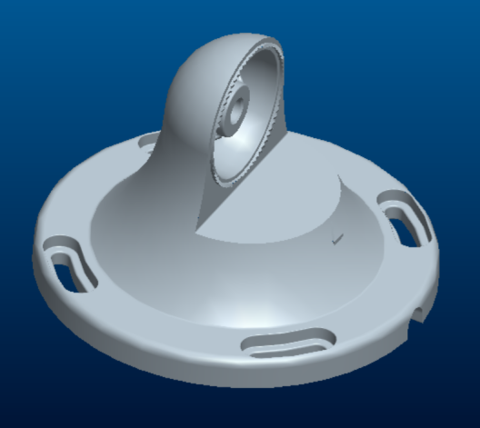
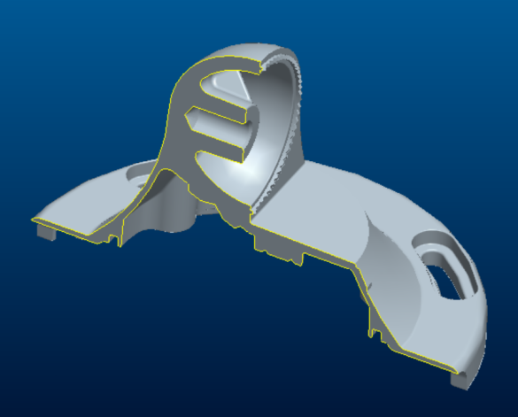
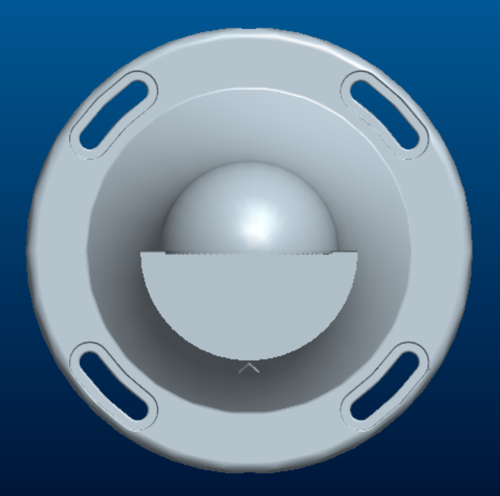
Scheme 1↓
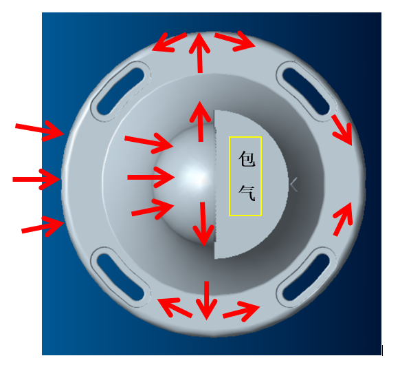
Scheme 2↓
Scheme 3↓
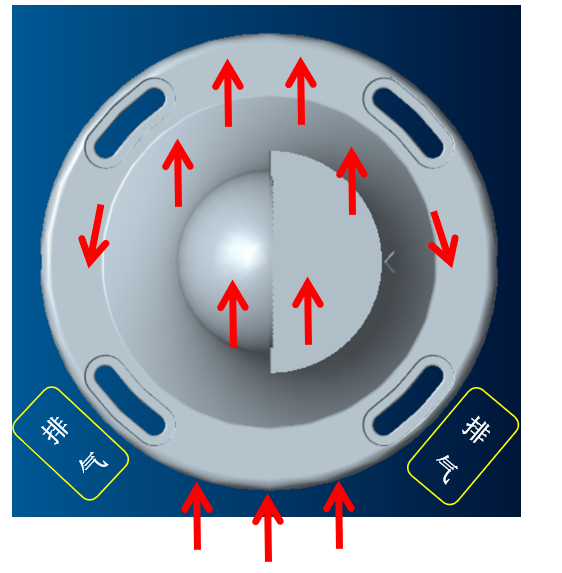
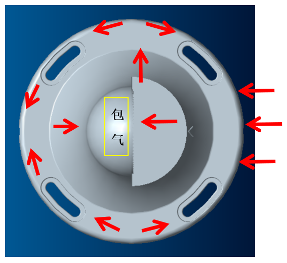
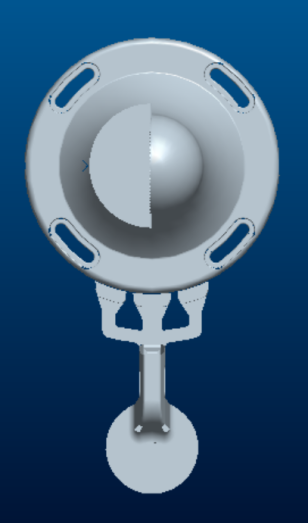
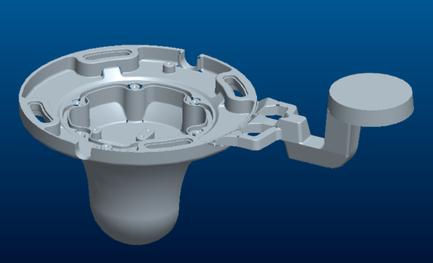
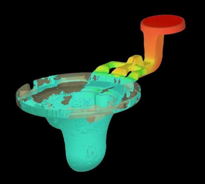
It is difficult to avoid the aeration of the small plane in scheme 1, and the last filling of the hemispherical top in scheme 2. Only scheme 3, not only can avoid the above two situations completely, but also can control the whole filling state well. Therefore, after comparison and analysis, scheme 3 is the best.
———————————————————————————————————————————————————————————————————————————
Example 2
Scheme 1↓
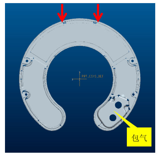
Scheme 2↓
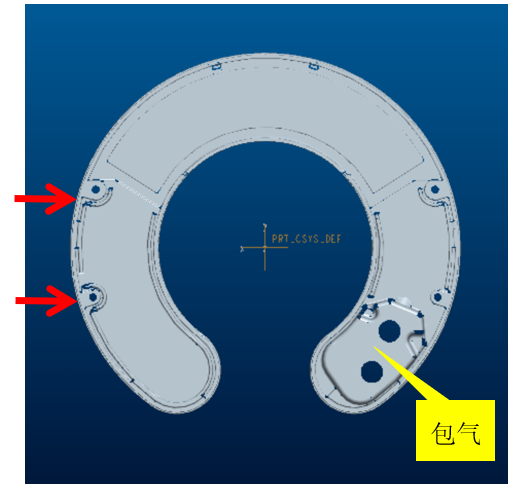
Scheme 3↓
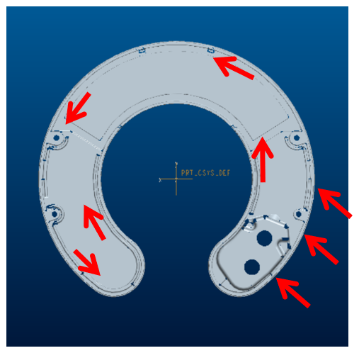
Scheme 4 ↓
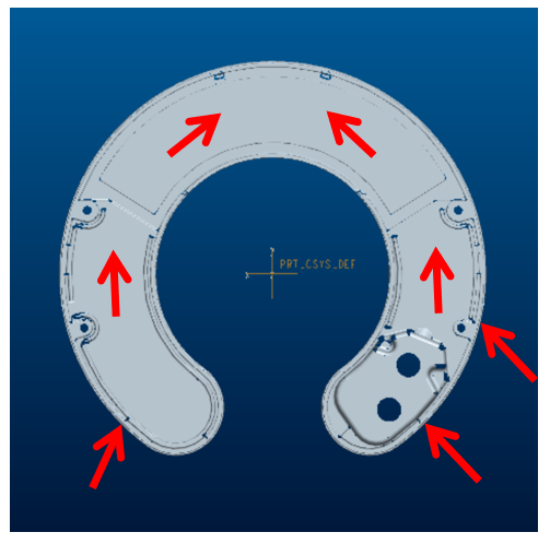
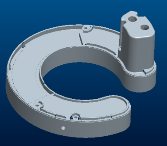
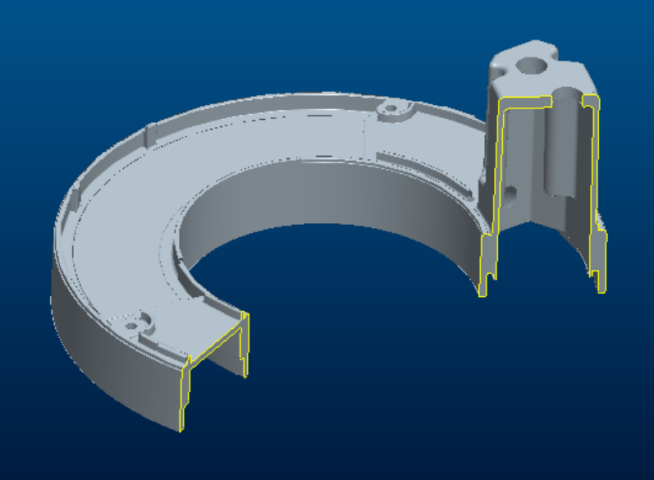
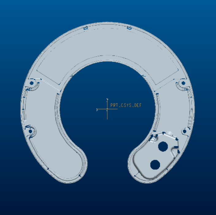
Both scheme 1 and scheme 2 inevitably form aeration at the top of the boss. Both scheme 3 and scheme 4 can solve this problem. Compared with this two schemes, the process of scheme 3 is longer and the number of refractions is more. The flow of scheme 4 is short, the number of refractions is less, and the flow pattern is easy to control. Therefore, after comparison and analysis, scheme 4 is the best.
—————————————————————————————————————————————————————————————————————
Example 3
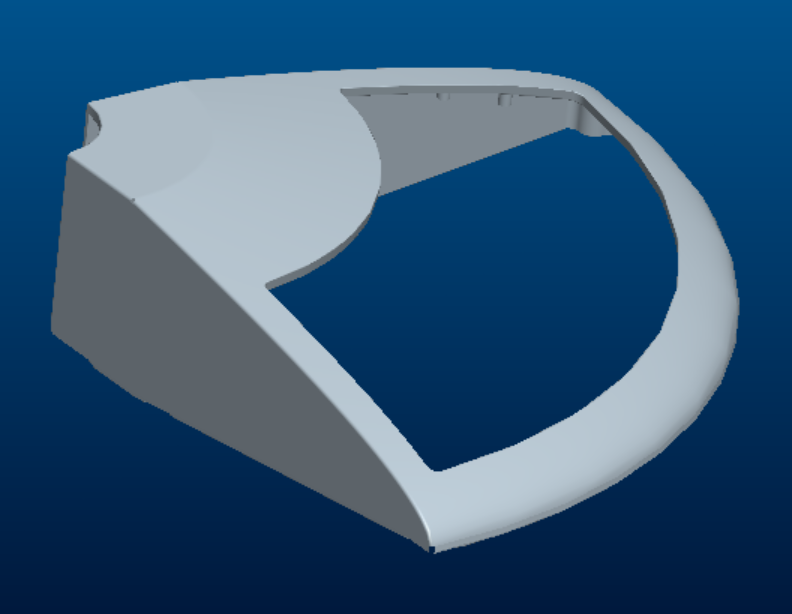
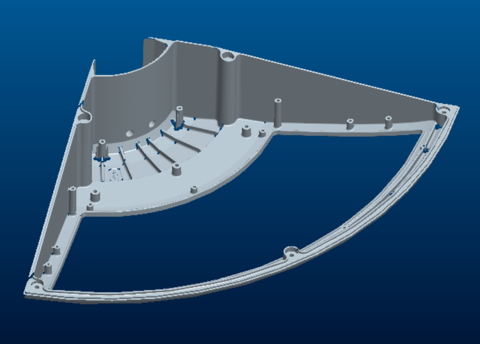
Scheme 1 ↓
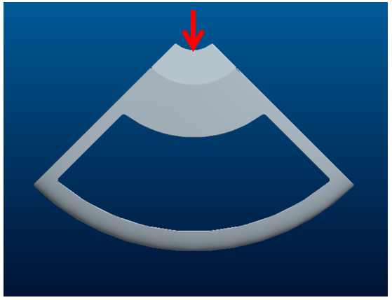
Scheme 2 ↓
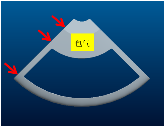
In scheme 1, the water inflow is too narrow and the flow rate is not enough to meet the filling requirements. The scheme 2 has very high requirements for the design of flow channel. If there is a slight deviation, there will be trapped gas. And the adjustable process space is limited. Therefore, both schemes are not ideal.
Scheme 3↓
Scheme 4 ↓
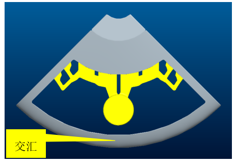
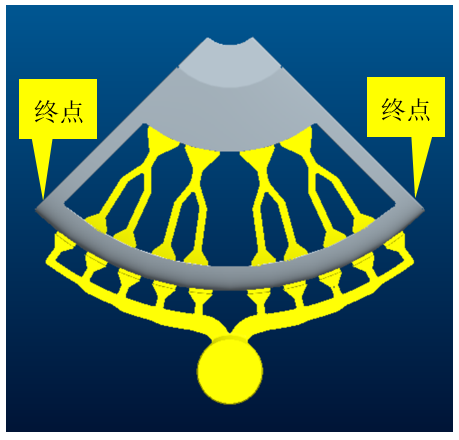
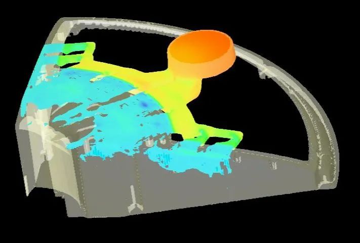
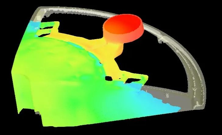
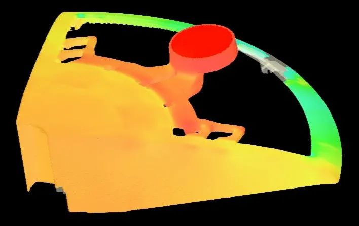
The aisle in the middle of scheme 3 lengthens the filling process, which is not conducive to the transmission of pressure. When eddy current is generated on both sides of the product at last, it is impossible to eliminate die casting defects by increasing the pressure. Scheme 4 can solve these problems completely. Moreover, the structure is very compact. Therefore, after comparison and analysis, scheme 4 is the most reasonable.
—————————————————————————————————————————————————————————————————————
Example 4
Scheme 1↓
Scheme 2 ↓
Scheme 3↓
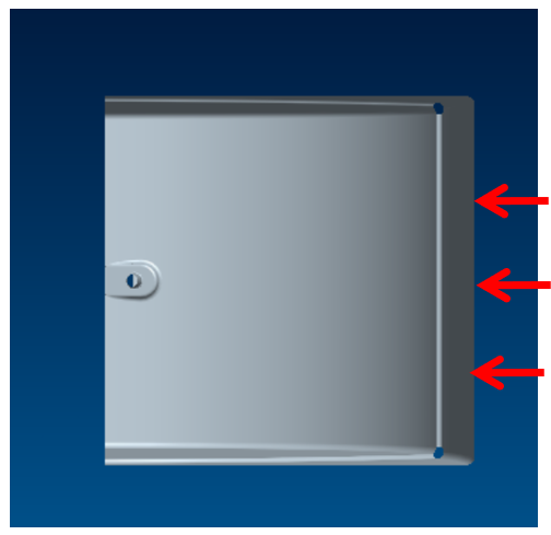
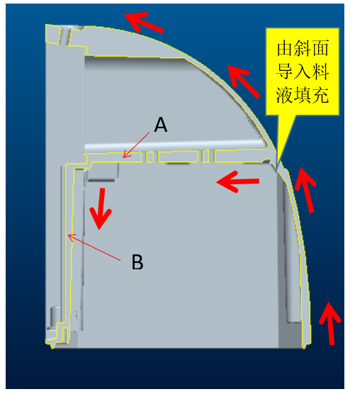
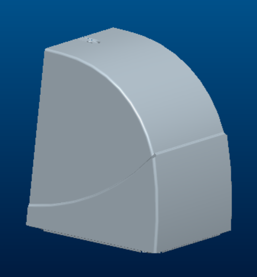
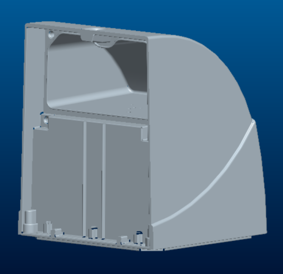
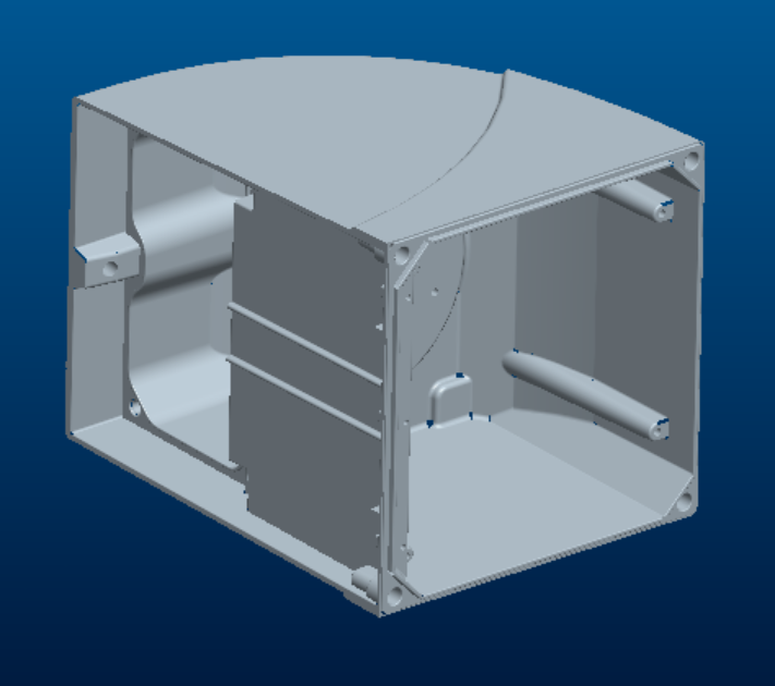
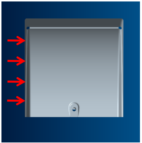
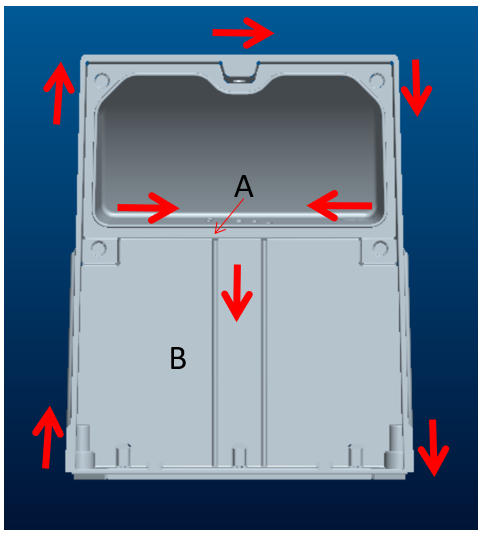
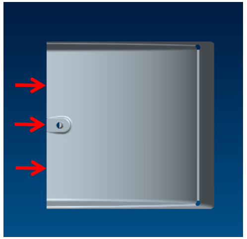
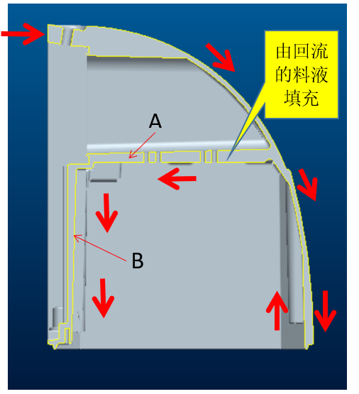
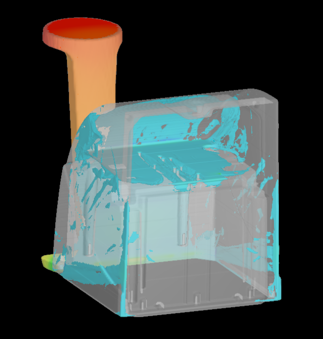
The biggest difficulty of this device is to solve the problem of filling on both sides of A and B, and to avoid gas trapping. In the scheme 3, a small slope is specially added to the feed liquid, which successfully solves the problem. And other solutions, even if added slope, also impossible to achieve. Therefore, the scheme 3 is the most reasonable.
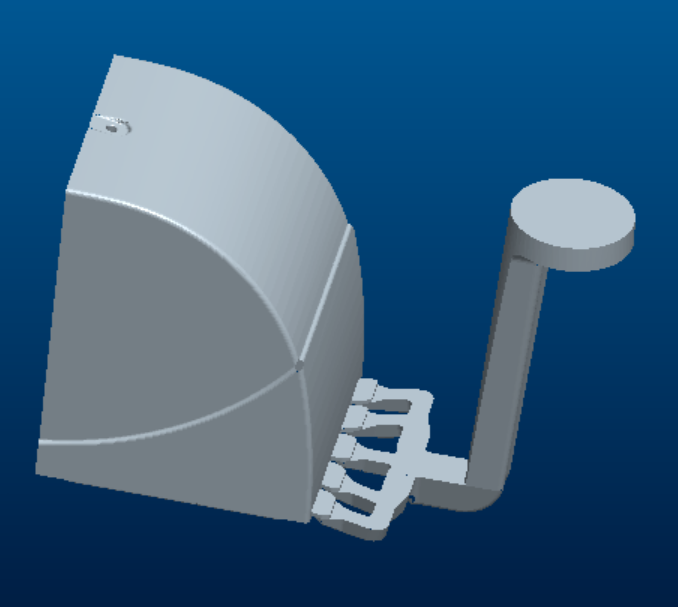
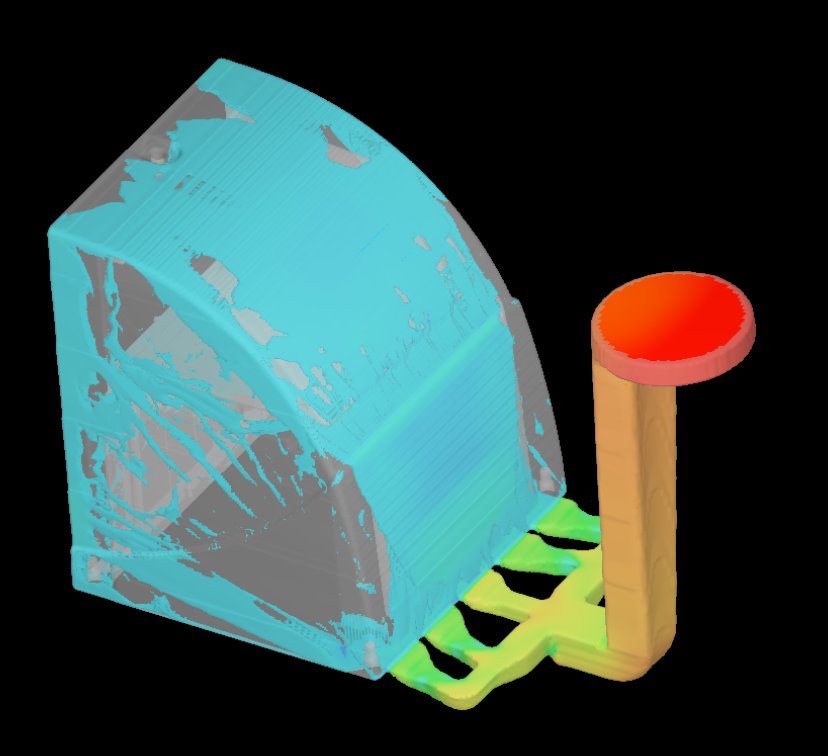
———————————————————————————————————————————————————————————————————————————
Example 5
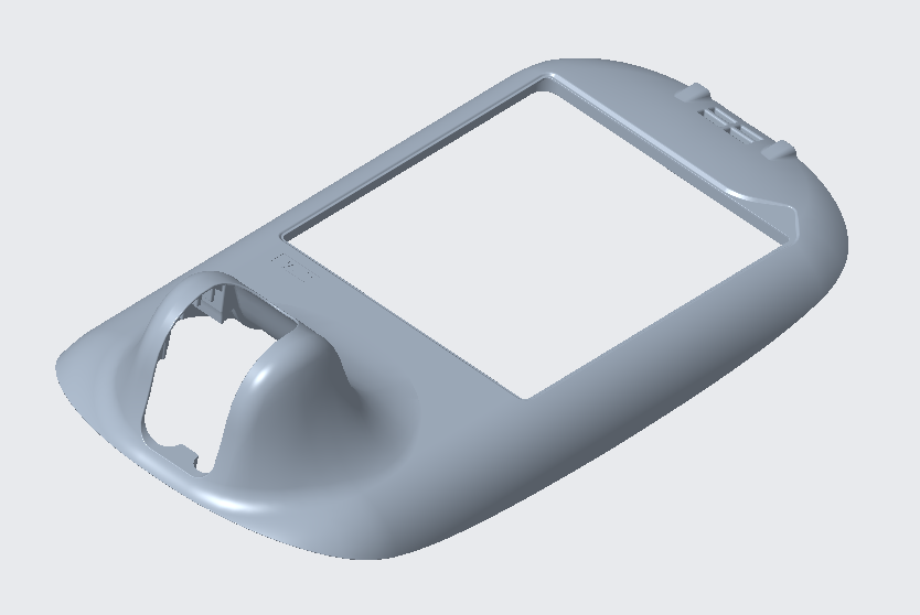
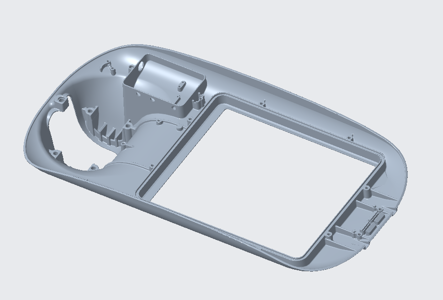
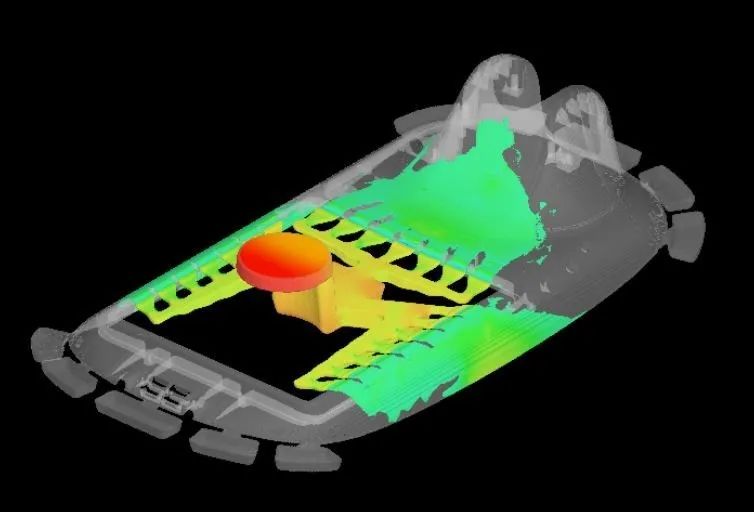
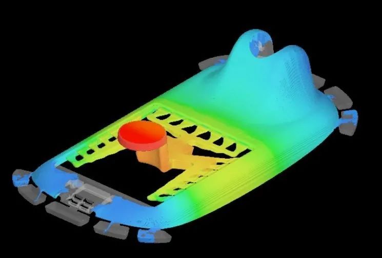
Before determining the feeding scheme of the mould, we must "get out" and get rid of the "bondage" to see clearly and comprehensively and get the correct results. Jump out of the "boundary" to get the "right result"!